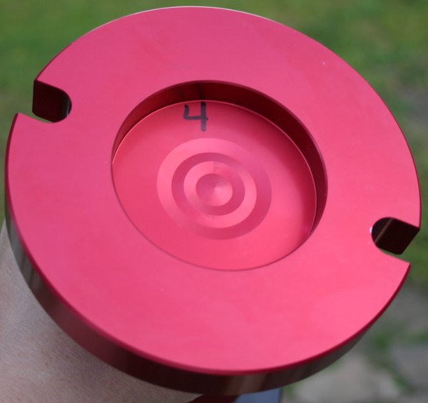
Here's what the bottom of the Browell tool looks like. I think the contact's being made by a thin ring of surface area around the number "4."
Thanks for considering my latest scenario!
Robroy
Moderator: Ranchero50


That's a very smart idea FreakysFords, thanks! I wouldn't have thought of that.FreakysFords wrote:Robroy, were it me, I'd take the tool, the old crank and measurement from the new (or load engine back up for machine shop to measure) and have them turn out what tiny amount is needed for flush mounting.
Good points!FreakysFords wrote:Shims could get fiddly. A tiny amount off at the base would be greater by the business end of the tool (as you already know).
I think you're right!FreakysFords wrote:The forget it and let it go option wouldn't be an option given all the time, energy, stress, thought and money you have in your build to date.
That I'll do. I'll be curious to see if they've heard of this issue before. I could also ask Tom Lucas if he knows exactly where the crankshaft came from. If he did, that might be of interest to Browell.FreakysFords wrote:Regardless, I'd still call the tool company and report your issue. If nothing else, you might help out the next person.
That's an idea for sure! I'll see what they think.FreakysFords wrote:Best case scenario would be for them to pay the machine shop's bill for turning the tool.
Thanks for pointing this out! If I go this route, I'll be very careful to advise caution on this potential issue.FreakysFords wrote:If you have it turned by a machine shop, be sure to emphasize the importance of the non bolt end remaining true and round (so they don't chuck it so tight that it distorts).
Perhaps--that's an excellent idea Robert! I wouldn't have come up with that. Feeler gauges should be the perfect thing for this.DuckRyder wrote:I would go with B and/or C.
It is possible that you could use two equal feeler gauges as shims?
"fit is too tight" as opposed to... just touching on -one side- indicating something is crooked.Ranchero50 wrote: ...permanent marker and paint ...the tool black and once dry install it until it binds,
then remove and see where the marker is removed from the tool or transferred to
the crank {and/or bellhousing}. If it's a couple scrapes it should show up as marking
on the crank {and/or bellhousing}, if it's all the way around then the... fit is too tight.
>Sorry Jamie, I don't understand exactly which diameters you're suggesting that I measure.Ranchero50 wrote:If you have a vernier caliper measure both diameters and compare,
same thing but different.
>I did! I'm sorry I haven't responded to your PM yet...Alvin in AZ wrote:Robroy, did you get my PM about it?
http://www.amazon.com/0-1-Dial-Indicato ... 605&sr=8-1


Fordnatic wrote:Toss the block!
Oh, actually I was refuting the above which states to throw the block away if it's off! I should have made my sarcasm more clear.70_F100 wrote:
Robroy, just put it together. The bellhousing is held in alignment by dowels in the rear of the block. If you're off by .020-.030", there's NOT going to be any problem.
There have been literally THOUSANDS of these engines assembled without checking the bellhousing alignment.
If it's off, you may as well throw the block away.
That measurement is not critical unless you're running a 10K RPM Hemi (or similar) engine.
Remember, "KISS"!!!
